

CONTENTS
- What is insulation resistance?
- Why is the insulation resistance test necessary?
- Principle of operation for Insulation Testers
- Insulation Tester types
- Standards and applications
- Testing points of insulation resistance
- Guard terminal
- Auto-discharge function
- Tools required for insulation test
- Insulation testing procedure
- Diagnostic insulation testing: PI & DAR
- Work safely!!!
- Kyoritsu Insulation Tester Line-up
1. What is insulation resistance?
Electrical resistance of an object is the opposition to the flow of an electric current passing through it. That is, objects with high electrical resistance, highly oppose the current flowing through them.
In electrical installations, there are parts of an electrical circuit or cable through which current has to flow with no resistance while there are some parts through which current flow needs to be inhibited in order to prevent possibilities of electrical shocks or leakage currents. Current will flow freely when using conductors with small resistivity as shown in the table below.
For example, when comparing the resistivity of copper which is: 0.0000000168 =1.68x10⁻⁸ Ω・m with the resistivity of insulators such as rubbers, which is: 10,000,000,000,000 =1013 Ω・m it is shown that current will find greater resistance to flow through rubber.
Insulation resistances are well over the resistances of conductors and it is normally expressed in MΩ (mega ohm): 1 MΩ which equals to 1,000,000 Ω.
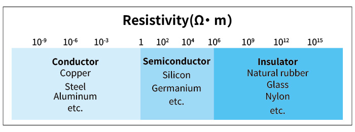
Generally, all metals like copper and aluminum can be considered as “good conductors”, which are widely used for wiring. On the other hand, rubber, glass and plastics are “good insulators” which are used to cover conductors and thus minimize the risk of electrical shocks and short circuits.
2. Why is the insulation resistance test necessary?
An electrical leakage may cause fire hazards and electrical shocks, thus the control of “electricity flow” is a fundamental safety issue. To prevent such dangerous situations, cables are insulated with resistant shielding to conserve the current flow along the cable. However, the cable insulation degrades with time as it is subjected to various stresses.
The main causes of degradation in cable insulations are excessive heat, moisture, dirt, chemical reaction, physical damage, abrasions, rodent activity, and overvoltages.
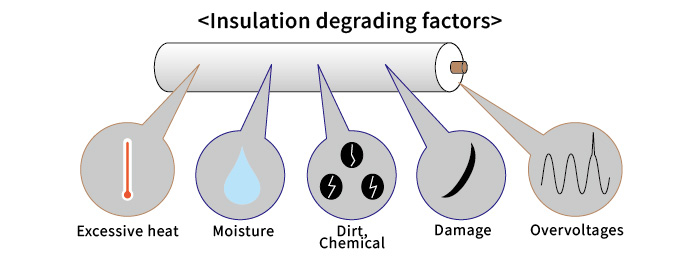
The electrical insulation degrades over a period of time due to natural and artificial aging processes. Excessive heat, moisture, dirt, chemical reaction, damage and overvoltages can all contribute to a premature deterioration of the insulation with a possible catastrophic result when the insulation breaks down. This happens when a significant amount of current leaks through the insulation causing serious consequences.
Routine and periodic insulation resistance tests need to be carried out to ensure that the insulation has not deteriorated. The value of the insulation resistance should be as high as possible, and should be checked by a non-destructive measuring method and must be conducted with DC voltage of a value which is higher or equal to the system’s normal operating voltage.
The devices commonly used for measuring the insulation resistance are called Insulation Testers.
3. Principle of operation for Insulation Testers
An Insulation Tester is a portable instrument that applies a DC test voltage, and subsequently displays the insulation resistance value in mega ohms, giga ohms or even tera ohms depending on the model. Insulation Testers make use of electronic technology to develop extremely high DC voltage tests with several hundreds of volts generated from the instrument’s battery.
This high DC voltage is applied to the device or circuit under test such that the Insulation Tester measures the current flowing through the cables and calculates the insulation resistance simply by applying Ohm’s Law.
An Insulation Tester mainly consists of a DC power supply, an Ammeter, and a switch to start or stop the measurement. Analog Insulation Testers display the leakage current by means of a needle pointer that deflects proportionally over a scale of insulation resistance values.
In the case of digital Insulation Testers, the insulation resistance value is shown as a digital numeric.
The device under test is connected with the Insulation Tester from the Line and Earth terminals. The measuring current flows through the earth terminal, the object under test and back to the line terminal.
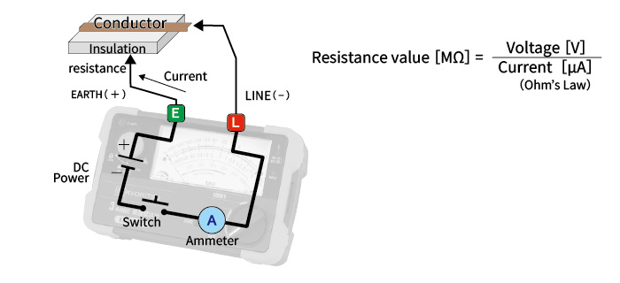
Conventionally the earth terminal of an Insulation Tester is the positive (+) side of the high voltage internal DC power supply, while the line terminal corresponds to its negative (-) side.
This is the recommended way to connect the terminals so as to obtain the most accurate results, i.e. connecting the conventional positive (+) terminal to the earth side of the device under test or to the earthed part of the device under test.
Effective Measuring Range of Insulation Tester
The effective measuring range is the range at which the accuracy of an Insulation Tester is guaranteed. There are two effective measuring ranges: the first and the second effective measuring ranges.
First effective measuring range is typically from 0.01 to 50% of the maximum reading of the tester (when there is no major scale division, the nearest major scale division is used.)
Second effective measuring range covers the scale divisions not included in the first effective measuring range.
Example: An Insulation Tester with a range of 500 V / 100 MΩ can have its;
- First effective measuring range: 0.1 to 50 MΩ (±5% of indicated value)
- Second effective measuring range: 0 to 0.1, 50 to 100 MΩ (±10% of indicated value)
Logarithmic scale
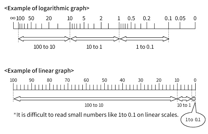
Analog Insulation Testers have a logarithmic scale since it is helpful to cover a wide range of up to 1000 times of the insulation resistance values. Logarithmic scales are useful to take readings precisely regardless of the pointer position.
4. Insulation Tester types

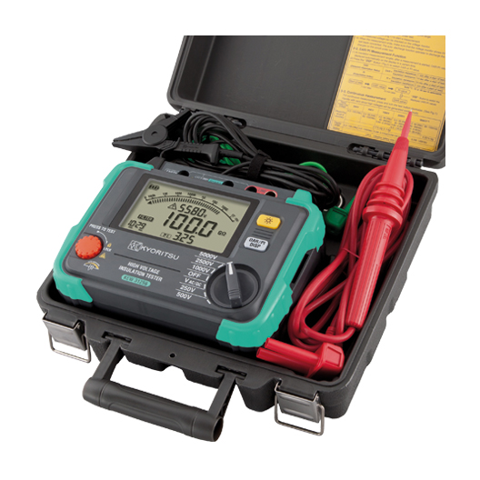
Several kinds of Insulation Testers are available covering a large variety of applications.
Insulation Testers can be classified by their rated test voltages:
- Low-voltage Insulation Testers (testing up to 1000 V)
- High-voltage Insulation Testers (testing over 1000 V)
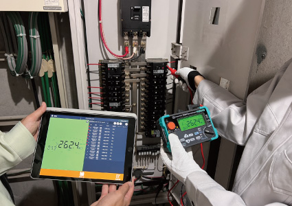
Insulation Testers can also fall into these categories:
- analog or digital
- an instrument with a single or a multiple test voltage range
- a dedicated Insulation Tester or a Multi Function Installation Tester that can perform other tests in addition to the insulation test such as RCD test and earth loop impedance test.
- an instrument that includes advanced diagnostic functions such as Polarization Index (PI), comparator, memory and connectivity to a PC, tablet or smartphone, etc.
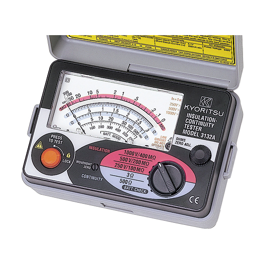
Analog indicator Insulation Tester
Digital multi-range &diagnostic Insulation Tester

Multi Function Installation Tester
5. Standards and applications
The International Standard of Electrical Installation of Buildings IEC 60364 has a dedicated section named “Verification”. This can be found in part 6. This section stipulates minimum values for the insulation resistance, measured with a particular test voltage, with no equipment connected to the circuits.
| Nominal circuit voltage | Test voltage in DC applied by Insulation Tester | Insulation resistance value |
|---|---|---|
| SELV, PELV( ≦50 V AC ≦ 120 V DC) | 250 V | ≧ 0.5 MΩ |
| Up to and including 500 V (including FELV ) with the exception of the above cases | 500 V | ≧ 1 MΩ |
| Above 500 V | 1000 V | ≧ 1 MΩ |
The testing apparatus (Insulation Testers) have to be capable of supplying an output current of at least 1 mA at its nominal test voltage.
According to IEC 60364, for a typical 230 / 400 V electrical installation (excluding SELV and PELV), requires that the insulation resistance at a test voltage of 500 V DC is larger than 1 MΩ.
A test voltage of 1000 V can be used for testing the insulation resistance of large electric motors, switchboards, industrial processing machines, devices and circuits with voltages exceeding 500 V (but below 1000 V AC and 1500 V DC).
A test voltage lower than 250 V (for example 15 V, 50 V, 100 V and 125 V) may be available in some Insulation Testers for testing the insulation resistance in telecommunication devices and circuits, security devices, local networks, speech (audio) devices, delicate electronic circuits and PCBs.
6. Testing points of insulation resistance
According to IEC 60364-6, the insulation resistance must be measured between each live conductor and the protective conductor or earth. In locations exposed to fire hazards, a measurement of the insulation resistance between the live conductors must also be taken.
As a general rule, it is very important that any insulation resistance test is carried out on circuits that are not energized i.e. not live.
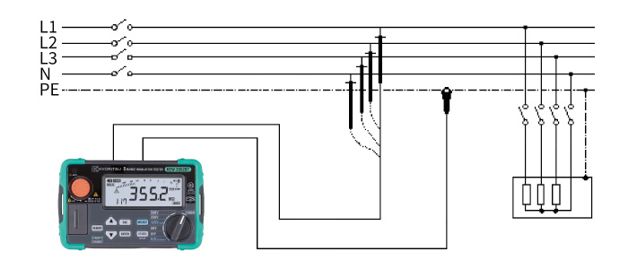
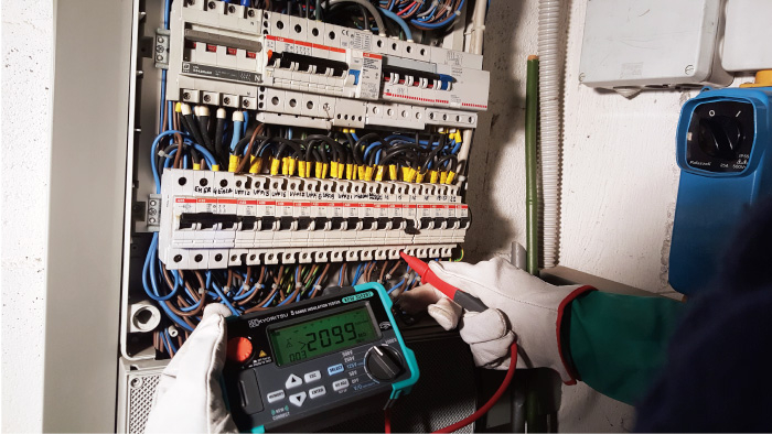
Example of insulation resistance test on an office switchboard
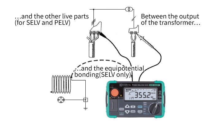
Even if the automatic disconnection of supply is normally the most common protection method, there are other protection methods like: protection by SELV, PELV or Electrical Separation.
In these particular cases the separation of live parts from those of other circuits can be confirmed only by measuring the insulation resistance. The resistance values obtained must be in accordance to the table in Chapter 5. An example showing the measurement of the insulation resistance confirming the isolation of live conductors from different circuits (i.e. primary and secondary sides of the isolation transformer) is shown in the diagram below.
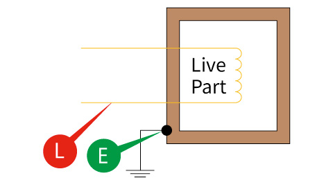
The insulation resistance between line conductors and protective conductors (earth / ground) has to be measured to ensure that no potential leakages or electrical hazards are present.
In order to complete the insulation test, connect the Earth terminal (E) of the instrument to the Earth of the installation under test and the Line terminal (L) to the line conductor(s) part and initiate the test.
The test must always be done with the circuit not energized.
D. Between live parts (between live conductors)
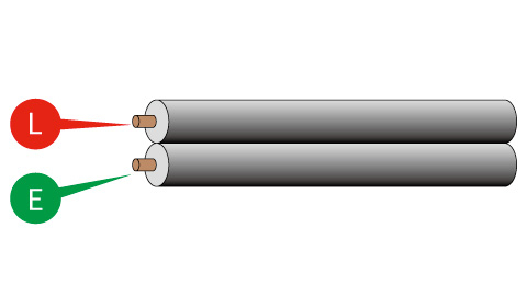
The insulation resistance between live conductors is measured to ensure that there are no short circuit risks between these conductors.
For electrical installations, this test is usually carried out just after the 2nd fix before any loads and electrical equipment are connected. In case the loads are already connected, the insulation resistance test will measure the resistance value up to the loads. It is nonetheless strongly recommended to disconnect any loads or appliances as the high DC test voltage can cause damage to these loads.
7. Guard terminal
High-end Insulation Testers, especially the high voltage types, have three terminals instead of the usual two. The third terminal is a guard.
Satisfactory insulation test results can be obtained without using this third terminal.
However, the guard terminal offers users an extra function for further diagnosis of the devices under test.
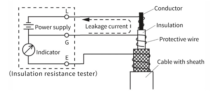
During an insulation test, if a leakage current flows through the surface of the object under test, the meter readings will be affected. Thus the guard terminal is used so that these leakage currents will be diverted around the measurement functions giving a more accurate reading of the insulation resistance.
Use of guard terminal (for Insulation Tester with a guard terminal)
When measuring the insulation resistance of a cable, some leakage currents can flow through the surface of the cable causing an error in the insulation resistance result. In order to prevent such an error, a conductive wire has to be wound around the point where the leakage current flows and then connected to the guard terminal as shown in the figure below. This will remove the unwanted effect of the surface leakages from the insulation resistance value of the cable under test.
8. Auto-discharge function
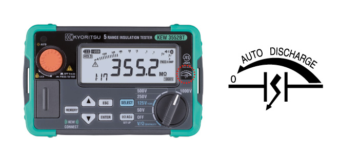
At the end of an insulation test, the object under test has effectively been charged in a similar way to a capacitor, with the insulation (of the object under test) behaving like a capacitor dielectric and the conductors as plates.
A professional Insulation Tester will automatically discharge the object or installation under test as soon as a test is finished to avoid any dangerous charges.
Some high end Insulation Testers also measure the voltage across the object or installation under test during the discharging process.
9. Tools required for insulation test
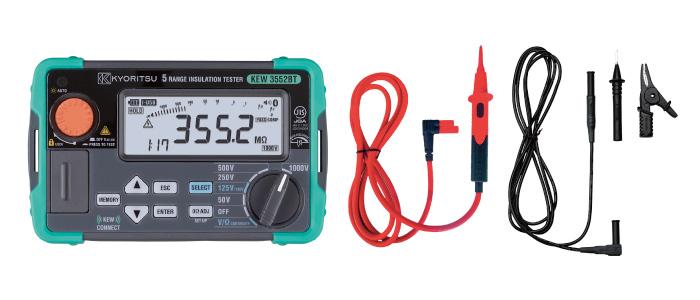
For an insulation resistance test it is necessary to have an Insulation Tester and its test leads (one for the Line and the other for the Earth) as shown in the figures below.
The alligator clip can be inserted on the black test lead, so that the operator does not have to hold the probe to the conductor.
In case the Insulation Tester is provided by the guard terminal a third test lead will be supplied (not shown in the below figures).
10. Insulation testing procedure
- Prior to testing, check the appropriate rated voltage which can be applied safely to the installation or device under test.
- For analog meters, adjust the Meter zero mechanism by using a screwdriver so that the pointer is over the “∞” symbol. Ensure that the meter is powered off when adjusting the meter to infinity.
- Check the battery voltage level. If batteries are exhausted or battery voltage level is low, replace all of them with new ones.
- Firmly connect the connector of test leads to the connection terminal on the meter.
- Select the appropriate rated measuring voltage.
- Short the ends of Line and Earth test leads together and press the Test button to confirm that the readings are approximately 0 MΩ.
- Press the Test button with the test leads open to confirm that the pointer of the analog tester is over the “∞” symbol or showing “OL” or “>” when using a digital meter. (Care must be taken because there is high voltage across the tips of test leads. Touching them will result in an electric shock.)
- Ensure the device under test is disconnected from the mains supply and confirm that its circuit is not energized.
- Connect the Earth cord (black) to the Earth of the circuit under test and the Line cord (red) to the test point without pressing the Test button.
- Press the Test button and record the displayed readings. (For analog tester, read the insulation resistance scale corresponding to the selected range.)
- Once the result is obtained, release the Test button and keep the test leads connected to the device under test until the tester has discharged the stored energy accumulated in the device under test during the insulation test. (Auto-discharging function)
- Disconnect the test leads when the discharging process has completed.
11. Diagnostic insulation testing: PI & DAR
The simplest insulation test, also called spot test, gives a reading of insulation resistance in MΩ. This test is applied for a short period of time, after which a reading is taken.
Generally, the spot test, specially on electrical installations or devices working under 1000 V, is well enough for understanding the condition of the insulation.
But for electrical installations or devices working at voltages higher than 1000 V where very high resistance readings are expected or in particular cases with very high and unstable resistance readings, to get the correct reading is not always so quick and simple by a spot test.
In fact, during the spot test specially with very high resistance readings we can note that reading is time dependent. The necessary time to get the reading goes from very few seconds up to one minute or more and it is due to the capacitive charging current to reduce.
Another factor which can affect the spot test with very high insulation resistance readings is the temperature. In fact, insulation resistance is significantly temperature dependent and in some cases we should apply correction factors to see more realistic values.
Therefore, for very high and unstable resistance readings other more advanced Diagnostic tests like PI & DAR can be of help. Such tests are available only on the high-end Insulation Testers.
Polarization Index (PI) and Dielectric Absorption Ratio (DAR)
PI and DAR are Time-Resistance tests and in fact they take successive readings at specified times and have the great advantage of being independent of temperature.
These diagnostic tests recognize the fact that "good" insulation will show a gradually increasing of insulation resistance after the test voltage is applied.
The insulation resistance is measured at two different times: normally at 1 min and 10 min for the PI and at 15 sec and 1 min for the DAR. Then the instrument divides later reading by the earlier reading, obtaining the result of PI and DAR on its display.
Diagnostic Insulation Tests
Polarization Index
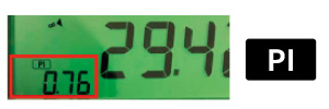
Polarization index = Insulation resistance value 10 min. after startInsulation resistance value 1 min. after start
| PI | 4.0 or more | 4.0 to 2.0 | 2.0 to 1.0 | 1.0 or less |
| Criteria | Best | Good | Warning | Bad |
Dielectric Absorption Ratio
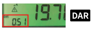
Dielectric Absorption Ratio = Insulation resistance value 1 min. after startInsulation resistance value 15 sec. after start
| DAR | 1.4 or more | 1.25 to 1.0 | 1.0 or less |
| Criteria | Best | Good | Bad |
12. Work safely!!!
*** Your safety depends on the combination of the right tools and safe work practices ***
There is no tool that can guarantee your safety if you do not follow a safe work procedure.
Here are few tips to help you in your work:
- Work on de-energized circuits (dead circuits) whenever possible.
- Use proper specific practices and procedures of Lockout/Tag out to safeguard against unexpected energization or start-up of machinery or equipment, or the release of hazardous energy during service or maintenance activities.
- If the above procedures are not in place or not enforced, consider the circuit as energized or “live”.
- On live circuits, use the following protective gear:
• Wear insulated gloves.
• Wear safety glasses or better, a face shield.
• Use insulated tools.
• Remove watches, bracelets or other jewelry.
• Stand on an insulated mat or insulating footboard.
• Wear specific flame resistant clothing.
Example of protective gears

13. Kyoritsu Insulation Tester Line-up
Kyoritsu offers a wide range of digital and analog Insulation Testers.
Digital meters display the measured values on their digital display making it simpler to read. Moreover, many instruments have useful functions such as memory and warning (comparator) functions, which alert the user when the measured value is lower than the pre-set value.
Analog meters are helpful to check the trend of insulation resistance condition by observing the pointer’s deflection.
Low Voltage
Analog type
| Range | MODEL | Rated voltage | ||||||
|---|---|---|---|---|---|---|---|---|
| 15 V | 50 V | 100 V | 125 V | 250 V | 500 V | 1000 V | ||
| 1 range | 3165 | - | - | - | - | - | ● | - |
| 1 range | 3166 | - | - | - | - | - | - | ● |
| 2 ranges | 3161A | ● | - | - | - | - | ● | - |
| 3 ranges | 3131A | - | - | - | - | ● | ● | ● |
| 3 ranges | 3132A | - | - | - | - | ● | ● | ● |
| 3 ranges | 3431 | - | - | - | - | ● | ● | ● |
Digital type
| Range | MODEL | Rated voltage | ||||||
|---|---|---|---|---|---|---|---|---|
| 15 V | 50 V | 100 V | 125 V | 250 V | 500 V | 1000 V | ||
| 3 ranges | 3005A | - | - | - | - | ● | ● | ● |
| 3 ranges | 3007A | - | - | - | - | ● | ● | ● |
| 6 ranges | 3551 | - | ● | ● | ● | ● | ● | ● |
| 6 ranges | 3552 | - | ● | ● | ● | ● | ● | ● |
| 6 ranges | 3552BT | - | ● | ● | ● | ● | ● | ● |
High Voltage
| Range | MODEL | Rated voltage | |||||||
|---|---|---|---|---|---|---|---|---|---|
| 250 V | 500 V | 1000 V | 2500 V | 5000 V |
1 k to |
10 kV | 12 kV | ||
| 1 range | 3121B | - | - | - | ● | - | - | - | - |
| 1 range | 3122B | - | - | - | - | ● | - | - | - |
| 2 ranges | 3123A | - | - | - | - | ● | - | ● | - |
| Variable | 3124A | - | - | ● | - | - | ● | - | - |
| 4 ranges | 3025B | ● | ● | ● | ● | - | - | - | - |
| 5 ranges | 3125B | ● | ● | ● | ● | ● | - | - | - |
| 5 ranges | 3127 | ● | ● | ● | ● | ● | - | - | - |
| 6 ranges | 3128 | - | ● | ● | ● | ● | - | ● | ● |